• Poor quality Ozito cordless drill charger

    An Ozito OZCD12V1A cordless drill came in to us for recycling and it looked like it had hardly been used.  Rather than recycling it I thought it might be a good candidate for repurposing or rehashing with different batteries.

    Photograph of a printed circuit board inside a power pack.
    Never been soldered!

    On inspection I found that the NiCd batteries were leaking (this may or may not be an issue since I have no idea how old it is) but more importantly I found that a wire on the transformer in the power supply had never been soldered at the factory!  It didn’t help that the circuit board on the transformer was only flimsily attached.

    The drill was hardly used, possibly because that batteries could not get charged?

    I don’t know how the mechanical side stacks up but the electronics is pared back to an absolute minimum.  Firstly, there is no filter capacitor in the charger power supply.  You can get away without one in some cases but it is usually good practice to have it.  The NiCd charging circuit is really basic.  Maybe even too basic to the extent that it may damage the NiCd cells.  It consists of six components, and two of those are indicator LED’s.  Having the two LED’s (one red and one green) is one positive thing.  Sometimes cheap products only use one.  Temperature sensing of the NiCd cells is also non-existent and that, coupled with the lack of battery voltage detection, means that the really basic charging regime will shorten the lifetime of the cells.

    It is a real shame that consumers demand cheap products and manufacturers supply them.  It is creating unnecessary environmental problems


  • Bang!

    This photo shows what a power surge can do. The fuse in this microwave oven absorbed so much energy that the end cap of it completely vapourised and shunted it along the fuse holder.

    A photo showing a 20=5mm ceramic fuse with a vapourised end cap.
    Bang!
    (check out the hardware bug)

    The body of the ceramic fuse remained intact which is what it is supposed to do

    It looks like the power surge was between live and earth because the capacitor (next to the fuse in the photo) had a very small eruption visible on its body.  It measured as 4nF and it is supposed to be 4.7nF.  The corresponding capacitor on the neutral side of the filter measured correctly as 4.7nF.  They are an X1/Y2 rated capacitor (as what would be expected) and it looks like it took the surge pretty well.


  • Repurposing – a good idea but usually too expensive?

    Here at Ecotech Services we like the idea of repurposing stuff as a way of stopping it going to the landfill but it seems that in most cases it is not something that makes us any money.  For example take a look at this Sony DCC-E455A mobile phone charger that came in for recycling.

    The isides of a Sony DCC-E455A car charger.
    The insides of a Sony DCC-E455A car charger.

    It puts out 4.5V at 500mA so it can be repurposed as a charger for newer phones. It looks like the maximum current on USB 2.0 is 500mA. So all that is needed is to look up the data on the chip (a JRC 2360AD), figure out how to change the voltage to 5V (a simple matter of putting a suitable resistor in the output voltage sensing circuit), and then fit a Micro B USB plug.

    This is an application circuit from the datasheet for a step down converter that is roughly the same as the one in the Sony charger.  The R1/R2 voltage divider would need adjusting to get 5 volts out.

    So lets do a costing for the repurposing:

    USB 2.0 Micro B plug    $3.76
    Resistor                $1.00
    Labour                 $34.50
    -----------------------------
    TOTAL                  $39.26 (New Zealand dollars)
    

    You can buy a new car charger for about $5 (although it would not be the same quality as the Sony product) so quite obviously repurposing is not a commercially viable option.  Also, this particular charger has the two halves welded together so it needed to be prised apart.  It would need to be glued back together after the modification.  This would make it a very unprofessional repurposing job.

    Another way it can be repurposed is to just use the circuit board itself as a DC-DC converter embedded into a piece of equipment.  It does not have to be a 12V input voltage because the 2360 chip can accept up to 40V, although a 35V electrolytic capacitor is used on the input. There may be other design considerations when running on a higher voltage such as the power dissipation by the chip.

    The conclusion for repurposing in this case? Obviously not commercially viable but something the DIYer or hardware hacker could do.


  • Dodgy diodes

    Here is a story for all you electronics techs.  And anyone making assumptions.  Most of us in other words.

    This is about a caddy type welder that came in for repair, a 180 amp inverter model. Can’t remember the make or model.   I checked for weld voltage and there was a healthy 80 odd volts coming out but there was a really pathetic spark from the electrode which meant there was next to no current.

    So I took it apart to do some fault tracing. Using a light bulb as a load I was getting 20 volts out on the weld terminals, down from the no load voltage of 80 volts.  Ok,  so is there a lot of resistance in the output, or maybe the inverter control circuit is doing something funny. Like a lot of these small caddy welders they have a centre tapped transformer and a full wave bridge rectifier arrangement.

    The full wave rectifier circuit is pretty basic.
    Image: Wikimedia Commons

    Even with the load in place I measured 80 volts AC on both sides of the transformer secondary.  All the connections were tight with no sign of heating due to contact resistance.  So was it a dodgy diode pack? It was a SOT227 package, which looks like the one pictured here.
    sot227-150x150
    I could measure the diode voltage drop in circuit of about 0.3 volts, which is what is expected for these Schottky diodes. Now normally semiconductors go short or blow apart and sometimes go leaky but if this diode pack is faulty it is as if it acting like a one way resistor!  Odd.

    Getting the diode pack off the heatsink was no mean feat with a mains filter capacitor, output current sense resistor, and output current bus bars all in the way.  With it out on the bench both diodes measured ok. We didn’t have one in stock and Tony suggested doing a DC check on it.  Putting about 30 volts up the anode and a 100 ohm resistor strung off the cathode I got nothing coming out of it!  I then remeasured the junction and it was now open circuit!  Definitely a dodgy diode (diodes actually).  When I remeasuring the junction voltage a bit later it measured ok.  Probably heat sensitive.

    So the moral of the story is that we cannot make any assumptions about how components fail.  Testing at all stages worked in this case in getting to the bottom of the fault pretty quickly.  When fault tracing I am sure we are all guilty of sometimes making assumptions and taking longer than it should to fix something.


  • Second hand can be more reliable than new

    Ecotech Services sells a range of second hand equipment that has been repaired or refurbished.  We can offer a warranty on the equipment without fear of incurring high costs (resulting from warranty repair or for refunds) to us for a number of reasons, including our experience on failure modes and the typical faults that are expected, and because of our judgement on where it lies on the bathtub curve.

    The bathtub curve is a concept in engineering that describes the reliability of a product during its lifetime.  It shows that a product is more likely to fail when it is very new or very old.

    Graph of the bathtub curve
    The bathtub curve is a concept that describes statistical chance of when a product fails at different points over its useful lifetime.
    Image: Wikimedia Commons

    In our experience the bathtub curve does appear to be applicable for a wide range of commercial, industrial, and consumer products.  However, since we don’t often have reliable data on total product sales versus number of product failures our evidence on the veracity of the bathtub curve is merely anecdotal.

    If the bathtub curve is valid for a particular product and we sell it during the constant failure rate section of the curve, then we can quite rightly make the claim that they are statistically more reliable than new ones.  This is assuming that we correctly assess that the product is not in the increasing failure rate of the curve, and that the manufacturer has sold the product with a minimal burn in.  These are both reasonable assumptions.


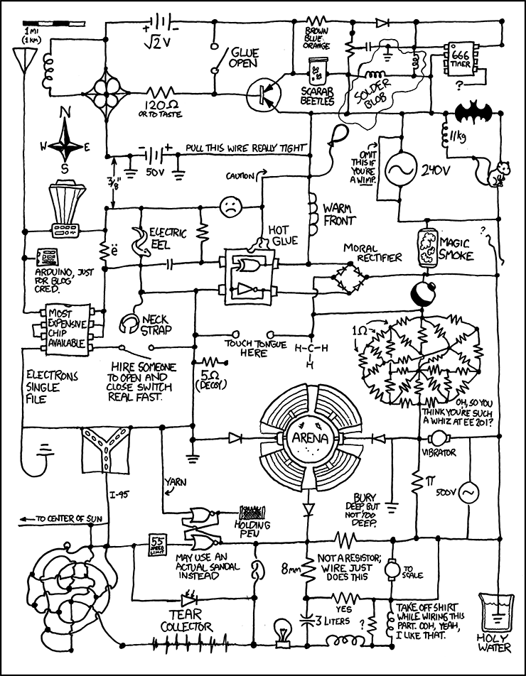
  • Check out this circuit

    I am having trouble doing fault finding on this circuit.
    Thanks to fotophil for alerting me to this rather interesting problem.

    A rather interesting circuit
    My knowledge of circuit theory is failing me. I don’t recognise some of those circuit symbols. And do Kirchhoff’s Laws, and Norton’s and Thévenin’s Theorems work on this circuit?
    Image credit: http://xkcd.com/730/